|
|
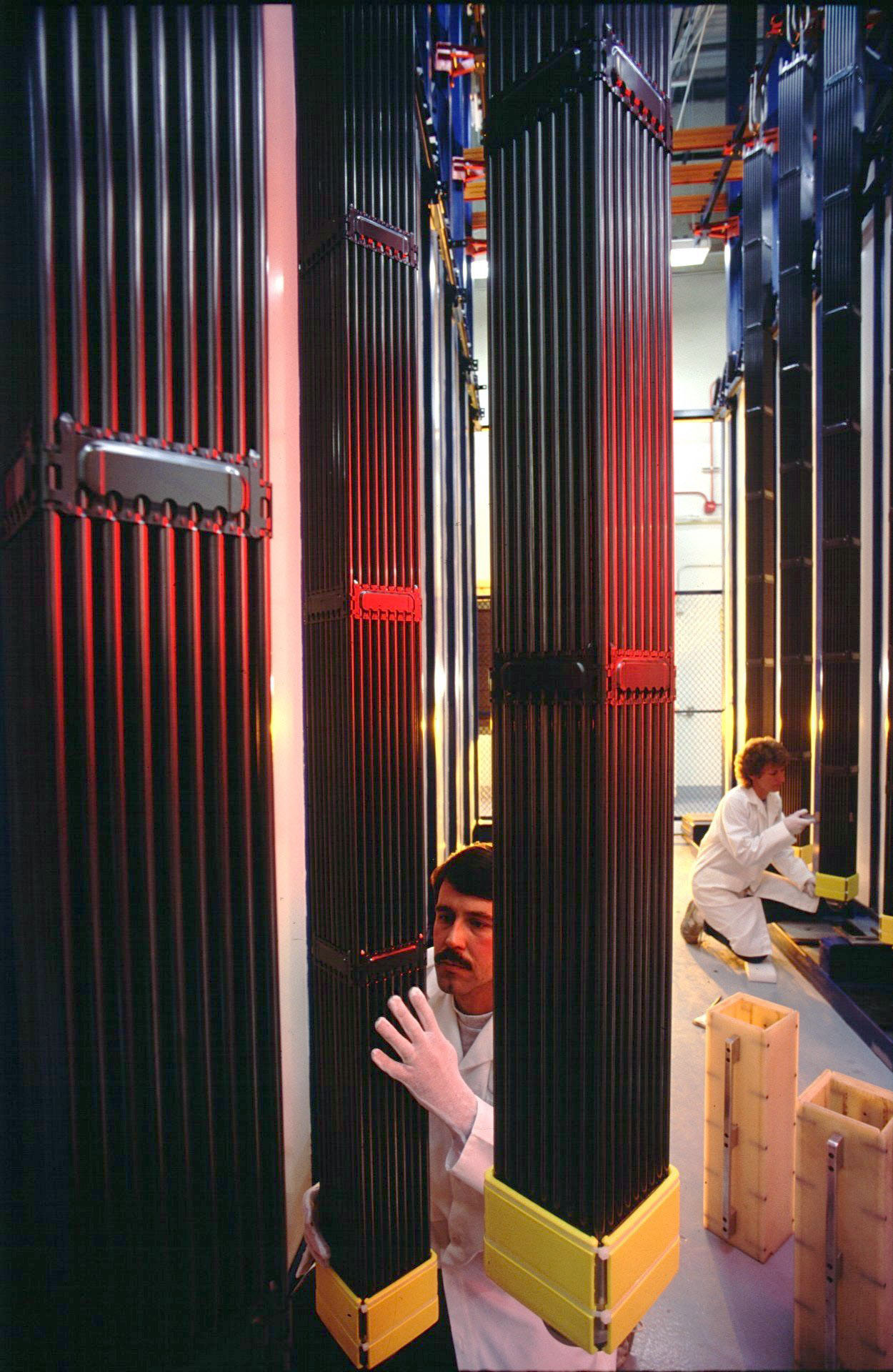
| Fig. 1: Nuclear Fuel Reload (Source: Wikimedia Commons) |
A nuclear power plant contains fuel, coolant, moderator, control elements and other materials. Fuels and the additional components of a power plant change during irradiation and therefore design must consider changes in thermal, mechanical, neutronic, and chemical properties, keeping in mind that a change in one property might impact another property. Fuel design is in a continuous process of improvement for the constant effort of better fuel utilization, enhanced heat removal, safer and more economical construction and increased operational efficiency. Fuel is consumed during fission and its composition changes during irradiation because of many interrelated phenomena, which degrades the nuclear fuel, eventually requiring its discharge from the reactor. After only one cycle, the fuel response to irradiation includes cracking due to thermal expansion coefficient differences at varying temperatures, pellet swelling, gaseous fission products and microstructure evolution. At the beginning of life, a fuel element is quite simple until irradiation brings about significant complexity arising from fuel fracture, fission gas, stress corrosion, cladding fracture and multidimensional deformation. [1]
Nuclear fuel management involves deciding the quantity and the attributes of the fresh fuel assemblies, the partially burnt fuel assemblies that will be reinserted, the core loading pattern and perhaps the control rod program strategy, for each reload cycle (Fig. 1). The objective of nuclear fuel management is to minimize cost while optimizing energy requirement, keeping safety as the prime determinant. Today, nuclear fuel management builds largely upon the software capabilities developed to complete core design. The advantage of building upon the software capabilities is that differences between different models like the light water reactor, the pressurized water reactor, and the boiling water reactor can be reconciled. [2,3]
The nuclear field cycle is the progression of nuclear fuel through the steps needed to attend to spent nuclear fuel. At the front end of this process is preparation of the fuel and fuel loading. There are a variety of variables that affect fuel loading including fuel enrichment, Re-load batch size-number of assemblies, fuel loading pattern of fresh and partially spent fuel assemblies, and control mechanisms. There are also a significant number of constraints for fuel loading such as lead time requirements of fuel fabrication, system power demand schedule, discharge burn-up of the fuel and the capacity of the reactivity control system. This leads to the optimal fuel reloading problem which is the problem faced when attempting to optimize the arrangement of all the assemblies - both new and old while still maximizing reactivity to maximize fuel burn-up and minimize fuel cycle costs. [4]
In nuclear technology, burn-up or fuel utilization is a measure of energy extracted from a nuclear fuel - the energy generated per unit of fuel consumed. It is measured in variety of ways including the fraction of fuel atom that underwent fission. Common Units are MWD/MTU-Megawatt days per metric ton of Uranium. Burn-up is limited by ability of fuel to sustain chain reaction (reactivity) and by radiation damage. Normally, 30,000-35,000 MWD/MTU is limit for thermal reactor fuel. [5]
A simple model of fuel reload is
 |
(1) |
On each cycle (1/n)th of the fuel is replaced. Each fuel batch experiences a discharge burn-up of Bd and each fuel batch on each cycle experiences a burn-up of Bd/n. kreactor is the uncontrolled multiplication factor (excess reactivity), and ki is the infinite multiplication factor of a fuel batch (excess reactivity). The uncontrolled fuel reactivity is the average of the infinite multiplication factors of the n batches of fuel that reside in the reactor. The newer batches have greater ki and the older batches have lower ki, perhaps ki < 1. [6]
Uniform fuel depletion can be described as
 |
(2) |
k0 is the uncontrolled infinite multiplication factor of the fuel batch when it is fresh. Bn is the burn-up of the batch in a single cycle. The n refers to the number of batches that the reload scheme includes. The α is a constant of proportionality with units of 1/Bn. kF is the uncontrolled infinite multiplication factor necessary to sustain a chain reaction at the end of an operating cycle. [7]
The equation for single cycle refueling is
 |
(3) |
whhere B1 is the fuel burn-up capability
 |
(4) |
These equations show that fuel cycle decisions depend on many engineering factors, some of which are not related to the core itself. Effective approximation for the linear burn-up model or linear reactivity model is possible. [8]
In some reactors, two cycle refueling is required. At the end of each cycle one batch of fuel has been burned for one cycle and the other batch has been burned for two cycles. Thus there is 1/3 more burn-up per batch in the two-cycle reload. From the following equations we can determine that each batch in the two-cycle reload scheme is burned for 2 B2. This is in terms of the single cycle reload burn-up. The two cycle reload scheme gives 1/3 more burn-up of the fuel for the same initial and final multiplication factors k0 and kF, i.e. for exactly the same fuel.
Interesting areas to look into would be how a "n-cycle" fuel reload would work and the discharge fuel burn-up of n-cycle reload scheme such as Batch burn-up in single cycle and Discharge fuel burn-up. An interesting limiting case of continuous refueling is the burn-up obtainable for a given initial fissile loading enrichment is twice that obtainable by refueling an entire core at each refueling. To pursue this a Reduction of excess reactivity for n-cycle reload scheme is required which would allow a comparison to single cycle change in multiplication factor to be calculated. There are many tradeoffs in the number of cycles used in nuclear refueling. Shorter cycles have less excess reactivity to control but have more refueling downtime. Longer cycles have more excess reactivity to control but have less refueling downtime. In this paper, Multi cycle fuel reloads are compared to single cycle fuel reload as a reference and the limits of multi cycle reloads are computed using a linear reactivity model. [9]
© Caleb Kumar. The author grants permission to copy, distribute and display this work in unaltered form, with attribution to the author, for noncommercial purposes only. All other rights, including commercial rights, are reserved to the author.
[1] H. W. Graves, Nuclear Fuel Management (Wiley, 1979).
[2] D. R. Olander, "Fundamental Aspects of Nuclear Reactor Fuel Elements," Universitiy of California, Berkeley TID-26711-P1, April 1976.
[3] J. J. Duderstadt and L. J. Hamilton, Nuclear Reactor Analysis (Wiley, 1976).
[4] R. G. Cochran et al., The Nuclear Fuel Cycle: Analysis and Management ( American Nuclear Society, 1993).
[5] M. J. Driscoll, T. J. Downar, and E. E. Pilat, The Linear Reactivity Model for Nuclear Fuel Management (American Nuclear Society, 1991).
[6] M. D. DeHart, "Parametric Analysis of PWR Spent Fuel Depletion Parameters for Long-Term-Disposal Criticality Safety," Oak Ridge National Laboratory, ORNL/TM-1999/99, August 1999.
[7] M. DeHart, "SAS2D - A Two-Dimensional Depletion Sequence for Characterization of Spent Nuclear Fuel," Oak Ridge National Laboratory, 11 Nov 01.
[8] W. E. Gunson, J. D. Sutherland, and S. N. Tower, "Nuclear Reactor and Refueling Cell Arrangement," U.S. Patent No. 3,437,558, 8 Apr. 69.
[9] W. P. Gassmann, "Method For Fueling and Operating a Nuclear Reactor Core," U.S. Patent No. 5,677,938. 14, 14 Oct 97.