|
|
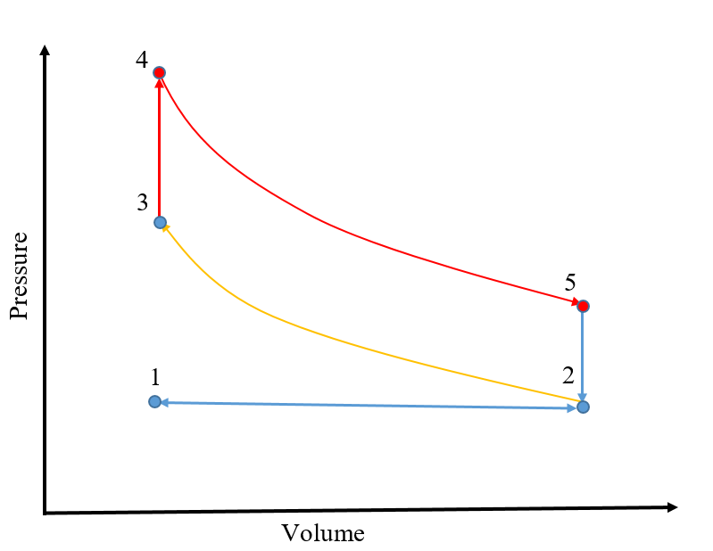
| Fig. 1: Otto Cycle for a Spark-Ignition Engine. [2] (Source: S. Cassady) |
The Internal Combustion Engine is one of the most important inventions in human history. It has revolutionized travel by car, by train, by boat and by air. There are two primary types of internal combustion (IC) engines: intermittent and continuous combustion engines. A four-stroke piston engine, for example, is an intermittent IC engine, while a gas turbine engine uses continuous combustion. IC engines utilize the combustion of fuel with an oxidizer to convert chemical energy into sensible energy and work. After ignition, the high-temperature gas exerts force on the piston or turbine as it expands, yielding useful work. The basic exothermic hydrocarbon combustion reaction (in air) can be written [1]
where w, a, b, c and d represent molar coefficients that depend on the specific hydrocarbon reactant and the amount of air present, the reactants wO2 + 3.76wN2 represent engineering air, and ε represents energy. [1] However, in practice, carbon dioxide, nitrogen, and oxygen are not the only products of combustion. Species such as nitric oxide (NO), nitrogen dioxide (NO2), and carbon monoxide (CO) are also common products of the reaction, and can be found in the exhaust gas of IC engines. [1] A brief look at two IC engines is presented here: a spark-ignition piston engine, and a gas turbine jet engine.
The thermodynamic Otto cycle describes the ideal spark ignition engine. The fuel-air mixture is drawn into the piston at constant pressure (1-2), and is then compressed isentropically until the piston reaches top dead center (2-3). The spark ignition of the mixture is modeled as a constant volume heat addition into the working fluid (3-4), which then expands isentropically (4-5) until it reaches bottom dead center (BDC). At BDC, heat is rejected at constant volume, and the exhaust gas is then expelled at constant pressure. A schematic of the Otto Cycle is shown in Fig. 1. The ideal work output of the cycle is the area enclosed by the process path.
In a real spark-ignition engine, the idealized constant volume heat addition is replaced by the combustion of fuel. In order to approach ideal conditions, current research looks to homogenize the fuel mixture in the combustion chamber, as well as study the ignition delay time, flame propagation, and other combustion characteristics.
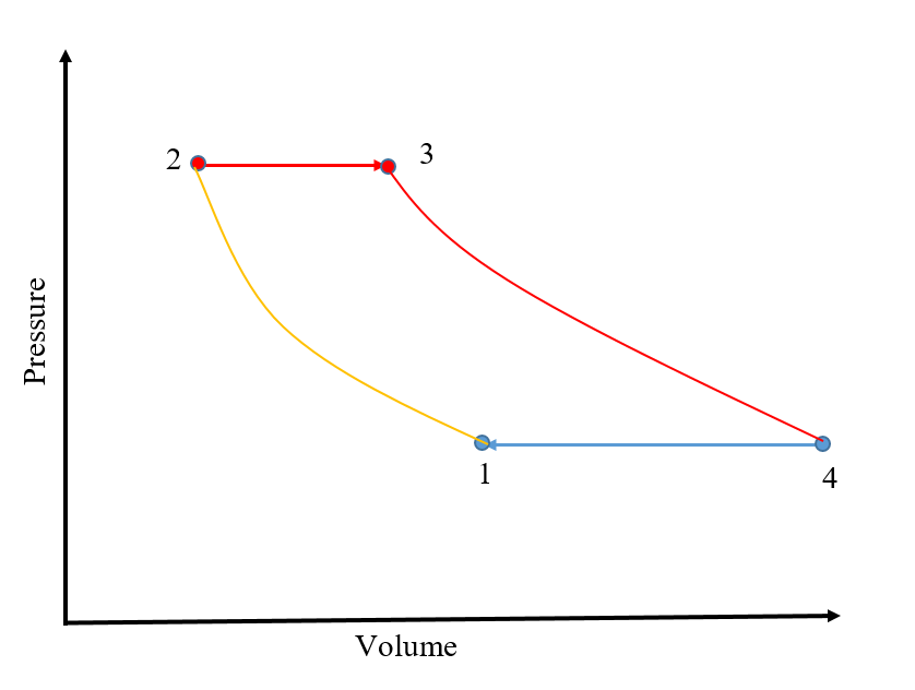 |
| Fig. 2: Brayton Cycle for a Gas-Turbine Engine. [2] (Source: S. Cassady) |
The gas turbine engine is ideally modeled by the Brayton thermodynamic cycle. [2] Air enters through the inlet, is compressed isentropically (1-2), and mixed with fuel. [2] Heat is added at constant pressure in a process that models the ideal combustion of the fuel (2-3), and the gas expands adiabatically through the nozzle (3-4). [2] The process is shown in Fig. 2. As with the Otto cycle, the ideal work output is the area enclosed by the process path.
A real gas turbine engine contains an inlet, compressor, combustor, turbine, and nozzle. [3] The turbine is connected to the compressor so that gas moving through the turbine drives the compression stage of the engine. [3] Air enters through the inlet and feeds into the compressor. The compression often occurs in multiple stages. Once compressed, the air is mixed with fuel and enters the combustion chamber. [3] The high-temperature gas rushes through the turbine and expands through the nozzle. [3] The entire process occurs continuously, with gas flowing through the engine without interruption. [3]
A thermodynamic analysis of spark-ignition and gas turbine engines reveals the general processes by which each convert chemical potential energy into propulsive work. Understanding the real chemical reactions at work inside the engines give insight into the combustion process itself, and formation of toxic and environmentally harmful gases. Improvements in efficiency and emissions reduction will require innovative research with a deep grasp of the thermodynamic and gas dynamics involved in internal combustion engine systems.
© Sean Cassady. The author grants permission to copy, distribute and display this work in unaltered form, with attribution to the author, for noncommercial purposes only. All other rights, including commercial rights, are reserved to the author.
[1] K. Wark, Advanced Thermodynamics for Engineers (McGraw-Hill, 1995), Ch. 10.
[2] Y. Cengel and M. Boles Thermodynamics: An Engineering Approach, 7th Edition (McGraw-Hill, 2011), Ch. 9.
[3] S. Farokhi, Aircraft Propulsion, 2nd Edition (Wiley, 2014), Ch. 4.